Friday, August 19, 2016

HAWT DIY Aug 2016 Data Collection

Made all the upgrades to the drive couple and have made some new runs.

The beautiful new couple.
Not visible is the spacer that takes the axial load from the spring part of the couple and transfers it to the end only.

Now that I don't trust the RPM meter I did some bench testing to get numbers to compare to the field tests.
Set up in the order that I write them down I have the meters.

I went with the INSPEED VORTEX "POLE MOUNT" ANEMOMETER a dramatic improvement over struggling with the lacrosse weather station.

So now the RPM meter is the weak link, it is so erratic that I can't use it. At home the bench tests are perfect but in the field it is terrible .


I'm not sure what to do about it.


The TSR is pretty steady at 5.2 so I'm happy with that.
And it looks like I can get to 13V @ 7MPH


Wednesday, July 6, 2016

HAWT DIY July 2016 Data Collection

Currently I am trying to figure out the refresh rate and the mode (such as Avg, or Peek) that the WS‐2813U‐IT La Crossei is set to, it seems to refresh every 15 - 30 seconds or so.


My analog volt meter is nice because is does the "averaging" for you with its slow and steady movements. (mounted in my old IPhone 3 box, saved for some such purpose)

So for a start I decided to assume that the La Crosse was averaging between refresh and so I would mentally average the volts thru that time.
This image shows 6.2 MPH and 16 VDC


 The data as collected (with about 50 data points) is Wind Speed x Volts

FYI, I'm going to say that start up speed is about 4 MPH


 I crunched the numbers and came up with a TSR of around 5.25, not bad.

Next step is to get a full length jumper cable to bring the Tach on shore and then to call La Crosse and see if I can get a tech to tell me the w/speed mode.

______________________________________________________________________________
07.11.16
Success today!
Yesterday not so much, the couple between the generator and the main shaft cracked as soon as I applied the dummy load. I discovered that I nicked the spring like milling when I drilled it out to receive the main shaft and a week of spinning got it all ready to snap as soon as I applied the load.
This is very good because it shows the weak spots in the design and all of the winter fixes whould be major improvements.
I replaced the couple and all is well for now, I do not expect the new couple to last much longer... we shall see.
With the ammeter spliced in to the system and my dummy load box set to 10 ohms I got a really nice correlation between vdc and amperage, unfortunately the tach is acting very flaky and so now that is harder to get a good number than it should be.


This chart starts to confirm actual output.

07.11.16_________________________________________________________

The new couple lasted about a day but I got some more data from it before it broke.
With new couples and a redesigned main-shaft I will try again in a month.

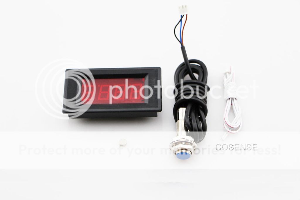
I have ordered a wired anemometer so that part of the puzzle will be addressed.

I am already planning how to install a bigger stepper generator, I feel that this one will not get me to the 16vdc often enough.


This chart indicates that it should take 12mph to get to 16vdc but I know this data is vague, might be more like 16mph.

I am missing a beautiful 16 - 18 mph day due to the drive train failures so I hope we get some wind in August.

07.17.16______________________________________________________________________

Repaired in one 3 hour session in the shop back at home.
The old couple was hand made (not by me) and both cracked.

Ordered two new ones and installed one with some significant detailed changes to limit the stress on the couple itself.


Sunday, July 3, 2016

HAWT DIY Summer 2016 Test Run

Finally got the system into the water.

Fully tested the Hall effect tachometer and the volt meter connections and all are working fine.

For the wind speed I am using an anemometer from a remote weather system. I have it attached to the tower below the blade; not the best location but for now ,OK.

Maybe I will try and attach it to the housing nose cone but that will throw off the wind direction readings (I don't really need that data.)

Went thru a complete final check of all the fasteners before closing it up for the last time.
Had to create a tool box dedicated to the project.
Created several jumpers for quick connection to the various instruments.
While standing in 2' of water, you need to pay close attention to every move you make and so the on-shore preparations are important.

I have an analog volt meter but it goes only to 30vdc.

Then I have the Tach revised to work out side in brilliant sunlight. A word to the wise, red LED CANNOT be seen in daylight!! I was lucky to have built it into an oversize box and so actually dropped it down into the shadow of the opening and it is fine.

Soon, very soon I will have an assistant aid in the data collection and we will have some numbers regarding the blade design and overall efficiency.


Sunday, March 20, 2016

HAWT DIY Vert. Axis Rotary Contact - 5 leads

The need to have additional data from the horz. axis forced me to go for a larger rotary contact.
I learned a lot from making the 2 lead rotary contact and refined the design so when I need to go to 6 it will be just an expansion of the 5.

Adding a hall effect sensor requires 3 more contacts.

Hopefully this new set up will work.

The mounting for the sensor.

Mostly complete rotating and stationary parts.

The lower end, I used a spare thrust bearing so no downward force on the system will be able to grind the plastic parts together.

5/8" OD pvc is perfect because the 21/32" of the shelf brass tube slides over it.
5 discrete, different length connections drop down from the inside,  1/8" brass tube is perfect for 4 - 40 screw threads.
Again, everything is designed to be robust, repairable, disassemble-able, and big enough that I can make it with out tweezers.

Machining the holes for the 5 identical rings that are loaded onto the tube 0.75" x 72 degrees apart.

Machining the 5 slots was as usual all about set-up; the set-up took an hour, the machining took 10 minutes.

Complete assembly


A little run-in for the commutators.

The anti rotation pin and receiver in place so as a module I can slide it off for service.


With the tower adapter attached.

Typical pin-out.


Test fit of the H/E sensor bracket.

A nice bit of success; have verified that the Sherline RPM gauge and the 4 LED RPM gauge collateral exactly, this is very good.


Also the output as measured from the rotary contact is identical to the earlier Sherline bench test.

System "Bench" test.


Interestingly the the stepper out-put is about 1 volt for every 10 RPM, anybody care to explain?